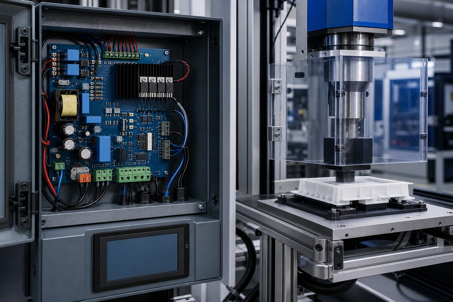
Our customer requested an Ultrasonic Welding Power Driver Board for a custom machine that joins thermoplastic parts. In the existing system, changes to the sonotrode, part geometry or operating temperature shifted the resonance point. As a result, a system driven at a fixed frequency could produce varying weld quality from one batch to another.
The requirement went beyond generating high-frequency power. The machine needed an electronic architecture that could find the resonance suited to its transducer assembly at start-up, monitor the electrical load during operation, rapidly protect the power stage under unsuitable conditions and interface with the production automation.
In short, the objective was a compact driver board that delivers controlled energy to the plastic joining process, adapts to load changes and protects itself when a fault occurs.
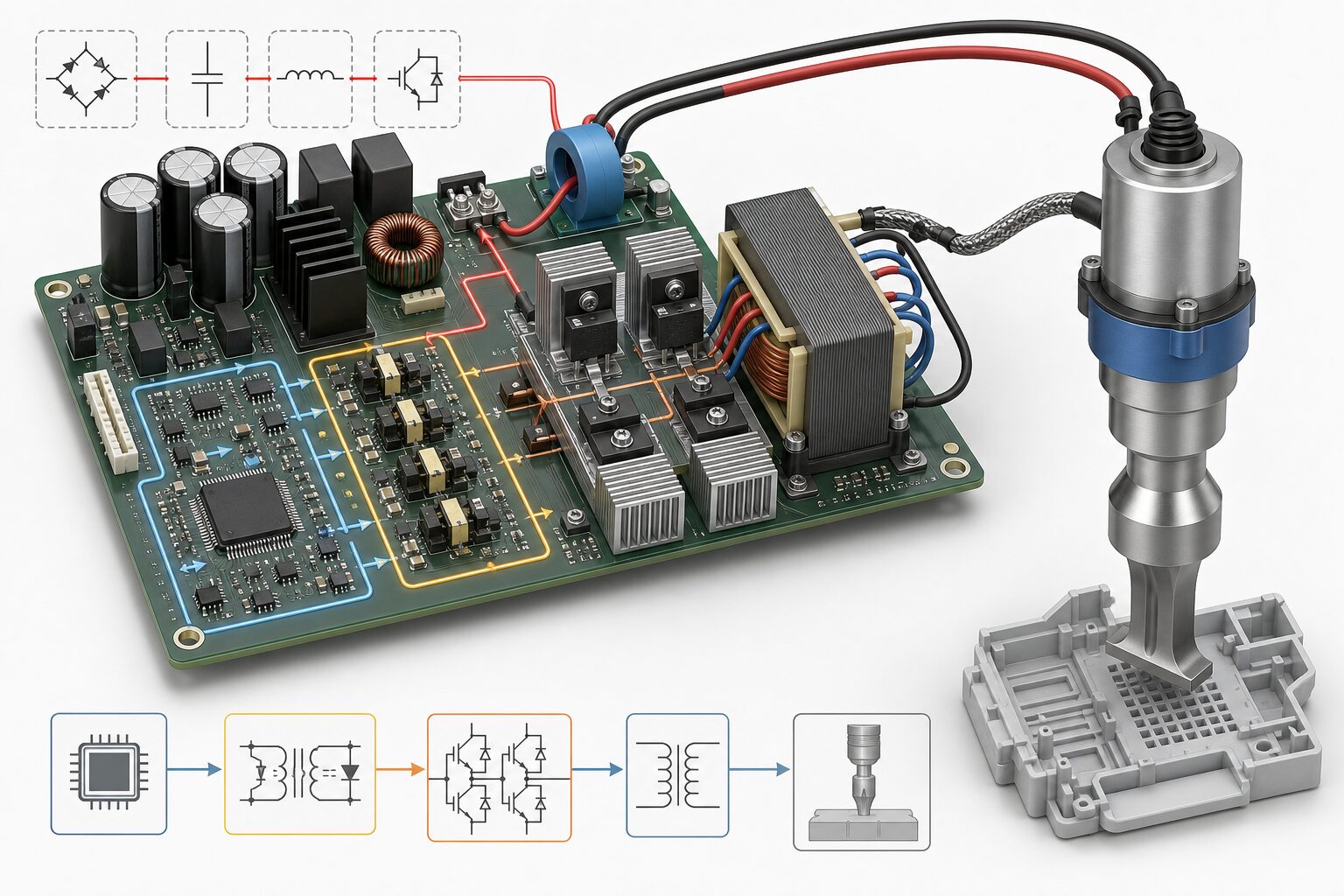
Revan Technology developed an application-specific driver board that integrates control and power electronics within one system architecture. Before each cycle, the board performs a short frequency scan to identify the operating point of the transducer-sonotrode assembly. During welding, it evaluates current, voltage and phase relationships and corrects the drive frequency within a defined window.
The welding cycle can be configured by duration, amplitude and an optional energy limit. Validated process values are stored for different part types, so the operator only needs to select the appropriate recipe.
Rather than acting only as an ultrasonic generator, the solution was designed as a process component that supervises the electrical indicators affecting weld quality throughout the cycle.
The DC bus is converted into application-specific high-frequency AC by a MOSFET full-bridge power stage. Isolated gate drivers, controlled dead time and low-inductance current paths are considered together to achieve safe switching. The PCB separates power and control zones and accounts for insulation distances, bus-capacitor placement, current return paths and airflow around the heatsink.
At the output, a matching transformer and resonance components sized for the application adapt the electrical drive to the transducer assembly. Mechanical guarding that restricts service access to high-voltage areas and a discharge arrangement are assessed together with the board’s installation inside the control enclosure.
Current and voltage samples are acquired simultaneously to calculate phase difference and apparent load. The operating point found during the initial scan is tracked in limited increments throughout welding. If it leaves the defined window, the cycle is not accepted as complete and a fault record is created. A single state machine manages soft start, the amplitude ramp, welding time and the hold signal.
A hardware overcurrent comparator disables the gate drivers independently of the software cycle. Embedded software supervises DC-bus undervoltage and overvoltage, heatsink temperature, transducer current and communication status. Isolated inputs and outputs carry PLC cycle signals, while RS-485/Modbus sends the recipe number, cycle result, energy indicator and fault codes to the supervisory system.
With the new driver architecture, the ultrasonic welding cycle changed from a fixed-frequency, operator-dependent arrangement into a controlled process based on measurable electrical feedback.
This project brings together Revan Technology’s custom PCB, embedded control and power-electronics capabilities to support quality, efficiency and risk reduction in plastic joining.
For customer confidentiality, the company name, machine model, power level and product names are omitted. Images are representative and illustrate the functional structure.
🔗 Get in touch with us:
Phone/WhatsApp: +41 76 212 8248
📧 E-Mail: info@revantechnology.ch
For detailed information about our services in electronics development & PCB design:
Revan Technology – Your partner for professional electronics and PCB development