 Emre Ceylan
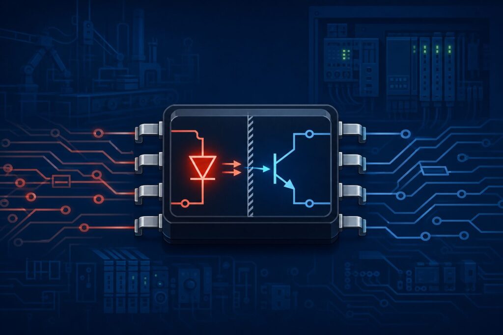
What is an optocoupler? In short, it is a galvanic isolation component that transfers signals via light between an LED and a photosensitive element, without a direct electrical connection between input and output circuits. It is widely used in industrial panels to create a safe interface between microcontrollers and high-voltage field circuits.
In Revan Technology's control board projects, the optocoupler is a fundamental design decision for both operator safety and protection of the MCU from field noise.
What is an optocoupler?
An optocoupler (optical isolator) is a semiconductor component that combines an LED and a photosensitive element (phototransistor, photodiode, or triac driver) in one package. When the LED on the input side turns on, the output side becomes conductive; only an optical link exists between the two sides.
Single-channel, multi-channel, and integrated driver variants are available. CTR (Current Transfer Ratio), isolation voltage, and propagation delay are critical parameters in selection.
Why is it important?
- It safely separates circuits at different potentials, such as microcontrollers and 24 V PLC, relay, or motor driver circuits.
- It prevents field noise, ground loops, and lightning-induced transients from reaching sensitive digital circuits.
- It creates an isolation barrier in applications requiring human safety and machine protection.
- It meets galvanic separation expectations in CE and industrial safety standards.
How does it work?
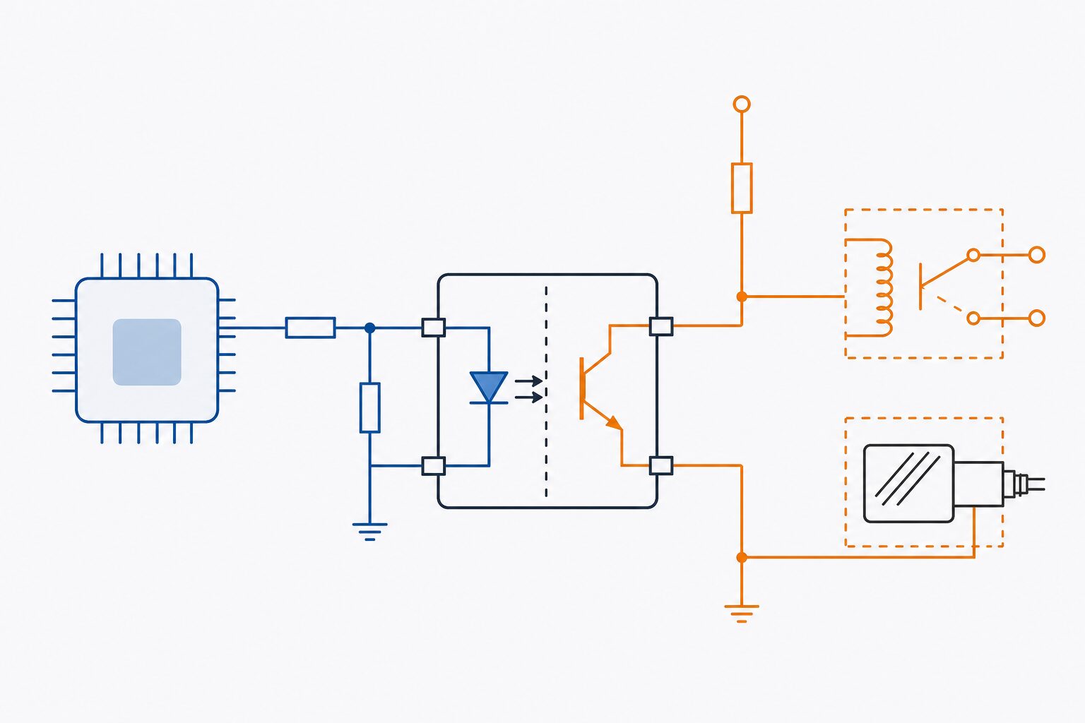
1. The MCU or input circuit supplies current to the optocoupler LED.
2. The LED light makes the photosensitive element conductive; an output signal is formed.
3. Input and output grounds are independent; a common ground is not required.
4. A pull-up resistor or driver circuit on the output side provides logic level or relay drive.
For PWM or fast digital signals, propagation delay and CTR degradation must be considered; if high speed is required, digital isolator alternatives should be evaluated.
Typical application areas
- PLC digital input/output cards and industrial I/O modules
- Motor driver and inverter interfaces
- Sensor and relay connections in GSM/IoT field panels
- Patient–device isolation in medical and measurement equipment
- Triac/MOSFET driver circuits on AC lines
Common mistakes
- Selecting resistor values without accounting for CTR degradation; signal loss at low temperatures.
- Connecting the input LED without a current-limiting resistor; shortening component life.
- Using a low V_iso rated optocoupler where high-voltage isolation is required.
- Choosing a slow optocoupler for fast PWM signals and distorting the waveform.
- Leaving logic levels unstable due to incorrect pull-up value calculation on the output side.
Selection / design checklist
- Is the required isolation voltage (V_iso) and creepage/clearance distance defined?
- Has CTR been calculated for LED current and temperature range?
- Is signal speed (propagation delay) suitable for the application?
- Have input limiting resistor and output pull-up values been verified?
- Is single or multi-channel requirement clear?
- Is a digital isolator needed instead of an optocoupler for fast digital lines?
FAQ
What is an optocoupler, in one sentence?
An interface component that transfers signals via light between an LED and a photosensitive element, electrically isolated from each other.
What is the difference between an optocoupler and a relay?
A relay performs mechanical switching; an optocoupler is a semiconductor, silent, faster, and has a longer life than mechanical relays. Relays are preferred for high-current switching; optocouplers for low-power signal isolation.
What is CTR and why does it matter?
Current Transfer Ratio is the ratio of output phototransistor current to LED current. At low CTR, the output may not conduct sufficiently; minimum CTR and temperature drift must be accounted for in design.
When should a digital isolator be preferred?
For MHz-level signals such as SPI, I²C, or high-speed PWM, optocoupler delay may be insufficient; capacitive or magnetic digital isolators should then be evaluated.
Conclusion
The optocoupler is a seemingly simple but critical isolation component in industrial electronics. With correct CTR calculation, isolation voltage selection, and output circuit design, both the MCU is protected and field reliability improves. Planning the optocoupler early in control board design is the most economical way to prevent field noise and safety issues.
🔗 Get in touch with us:
Phone/WhatsApp: +41 76 212 8248
📧 E-Mail: info@revantechnology.ch
For detailed information about our services in electronics development & PCB design:
Revan Technology – Your partner for professional electronics and PCB development