 Emre Ceylan
In industrial facilities, sensors, motor drives, power analysers and field panels must communicate at the same time — and rs485 industrial communication is one of the most widely used physical layers for carrying point-to-multipoint data. The long-distance reach and noise immunity that UART-based protocols (such as Modbus RTU) need in the field depend largely on the RS-485 differential bus.
When designed incorrectly, the same bus becomes the most expensive fault point in the project, with address clashes, reflection-induced distortion and communication dropouts.

RS-485 protocol — brief definition
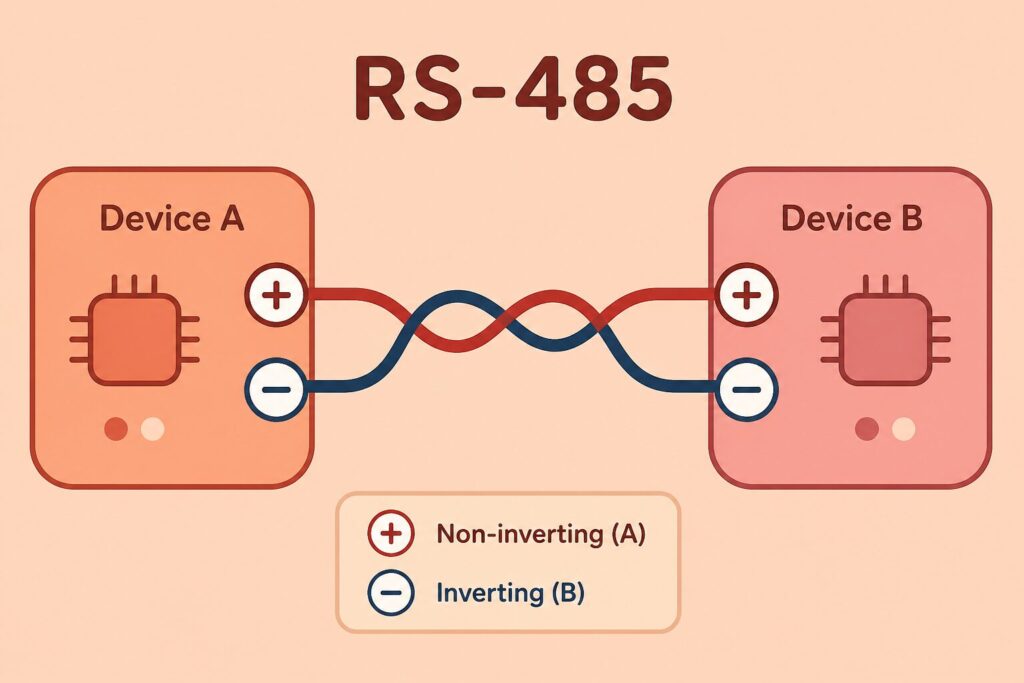
RS-485 (TIA/EIA-485) is a half-duplex serial communication standard based on differential signalling. Data travels as the voltage difference between the A and B lines; common-mode noise affects both lines equally and is rejected by the differential receiver. This is what makes it viable where single-ended UART signals fail — motor noise, welding interference and long cable runs in factory environments.
In practice RS-485 is usually not a “protocol” but a physical layer. Modbus RTU, BACnet MS/TP or proprietary device protocols run over the same bus through RS-485 transceivers. With correct calculation of node count, baud rate, cable length and termination, dozens of devices can be addressed safely on one bus.
Problem context
One of the most common sentences in field engineering is: “It worked fine in the lab, but on the panel floor it drops out randomly.” A root cause is trying to copy a short-range, clean-environment UART link one-to-one onto an industrial RS-485 line.
Single-ended TTL communication cannot go beyond a few metres, while RS-485 lines can span hundreds of metres. That advantage is not free. Common ground potential differences, wrong termination, star topology, excessive stub length and insufficient galvanic isolation show up in the field as frame errors, CRC faults and devices that “disappear”.
In distributed measurement nodes, energy monitoring panels and GSM bridge units — architectures Revan Technology works with frequently — continuity between the central controller and field sub-units directly drives downtime cost.
Technical analysis
The core elements of an RS-485 bus are:
1. Transceiver (MAX485, SN65HVD, ADM2483, etc.): Converts the microcontroller UART TX/RX pins to differential A/B lines. DE (Driver Enable) and RE (Receiver Enable) pins control direction in half-duplex operation.
2. A and B differential pair: Twisted-pair cable is preferred; equal-length stubs reduce line reflections.
3. Termination resistors: Typically 120 Ω at bus ends; absorbs reflections and preserves signal integrity.
4. Bias (polarisation) resistors: Pull-up/pull-down network so the bus is not undefined when idle; must be calculated carefully in multi-node systems.
Half-duplex operation: Only one device transmits at a time. The master sends a request, bus direction changes, the slave responds. In protocols like Modbus RTU, a 3.5-character silent gap is critical for detecting frame boundaries.
Speed–distance trade-off: At low speeds such as 9600 baud, distances approaching 1000 m are possible; at 115200 baud the safe span drops to a few tens of metres. Design should target a “sustainable field speed”, not the highest possible rate.
Galvanic isolation: Different ground potentials in the field can permanently damage transceivers. Opto or integrated isolated RS-485 drivers significantly improve reliability between power panels and measurement boards.
Field scenarios
Typical RS-485 situations in industrial projects include:
- “The Modbus device sometimes does not respond”: Termination is missing or only at one end; the waveform reflects and bit edges shift. The fault lies in the physical layer, not the protocol stack.
- “Adding a new sensor took down the whole bus”: Star topology or long stub cables disturb bus impedance. If devices are not on a single backbone (daisy chain), communication becomes unstable.
- “We grounded it, still errors”: Shield grounded at the wrong point or mixed with A/B increases noise. Shield is usually referenced at one end; the signal return path must be defined by design.
- “It fails at 115200 but works at 9600”: Cable capacitance and transceiver rise-time limits. Lower speed may be a temporary fix; the real cure is termination, shorter stubs and appropriate drivers.
This pattern shows that RS-485, although it looks like “just two wires”, demands electrical discipline.
Solution approaches
Engineering steps for a reliable RS-485 network:
- Topology discipline: Prefer a linear bus; avoid T-junctions. Limit stub length to a few tens of centimetres.
- Termination plan: 120 Ω only at bus ends; do not add random mid-bus terminators. Very short runs may need none — verify by measurement at the intended speed.
- Bias resistors: Central bias so receivers are not undefined when idle; recalculate values as device count grows.
- DE/RE timing: In software, disable the driver only after sufficient delay following the last bit; early disable truncates the final byte.
- Isolation and protection: TVS diodes, fuses and isolated transceivers are mandatory on sites exposed to switching and lightning-related surges.
- Protocol robustness: With Modbus RTU, use timeout, retry and CRC error counters; a single bad frame must not lock the entire system.
In Revan Technology field panels, these principles are applied early in design so communication between the central controller and distributed measurement nodes stays uninterrupted.
Benefits
Applying RS-485 industrial communication correctly delivers concrete project gains:
- Long-distance single bus: Aggregate multiple devices on one bus without extra switches or gateways.
- Noise immunity: Differential structure offers clear advantage over UART against motor and welding interference.
- Cost-effective infrastructure: Lower cabling cost where full Ethernet plant wiring is not required.
- Serviceability: Remote diagnostics, parameter read/write and firmware update (where designed in) via Modbus register maps.
- Scalability: New nodes can join the same bus architecture when the address plan is defined upfront.
Industry observation / experience
During field commissioning, a significant share of communication faults stem from line physics rather than device firmware. Skipping termination under pressure for a fast startup often leads to weeks of intermittent fault hunting. If a bus that is flawless at 9600 baud fails when the team moves to 115200, the issue is rarely a “Modbus bug”; an oscilloscope and termination checklist should follow.
In successful industrial projects, RS-485 is not two wires on the schematic but a system decision covering topology, grounding, isolation and protocol timing. That discipline directly raises uptime in distributed monitoring and automation panels.
Conclusion
RS-485 industrial communication is a proven physical layer at the heart of embedded and field systems. Its advantages — long reach, multi-device support and noise resilience — form a dependable infrastructure when combined with correct termination, topology and software timeout handling. Supporting bus electrical design with testing and documentation from the start, rather than treating it lightly, materially reduces communication risk in the field.
🔗 Get in touch with us:
Phone/WhatsApp: +41 76 212 8248
📧 E-Mail: info@revantechnology.ch
For detailed information about our services in electronics development & PCB design:
Revan Technology – Your partner for professional electronics and PCB development