 Emre Ceylan
50 Hz mains hum in analog inputs is one of the most common reasons an ADC reading that looks like a straight line on the lab bench starts oscillating once the panel is installed in the field. Mains harmonics, current flowing through shared ground, and long signal cables create millivolt-level ripple on 4–20 mA or 0–10 V lines.
Analog section layout and filter topology are defined during PCB design; sampling rate, averaging, and notch filtering are completed in firmware development. The examples below are compiled from commissioning and field service notes; no customer names or machine brands are included.

What is 50 Hz mains hum in analog inputs?
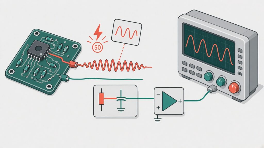
The 50 Hz (Europe) or 60 Hz (North America) mains frequency couples into the analog input line as magnetically induced voltage. In a single-ended ADC reading, the potential difference between the sensor signal and the reference ground carries common-mode noise as well as the measured quantity. The result: the ADC code swings ± a few LSB around a fixed pressure or temperature.
The noise source is often not the sensor itself; an in-panel power transformer, contactor coil, inverter, or fluorescent ballast couples magnetically from a power line running parallel to the sensor cable. A long unshielded cable acts as an antenna. On an oscilloscope, a 20 ms period (50 Hz) sine wave or its harmonics is clearly visible.
Problem context
In the prototype, the sensor sits next to the board with a short jumper; common-mode noise is low. On machine panel installation the same sensor arrives over 15 metres of cable, routed in the same tray as power wiring. The operator complains that “pressure is not stable” or “temperature is jumping” on the HMI. Recalibration looks fine on the bench; back in the field, the ripple returns.
Applying only a moving average in software increases latency; on fast process changes it delays the real step. Applying only an aggressive RC filter in hardware narrows bandwidth and softens pressure transients. The right approach is a layered solution matched to noise level and process dynamics.
Technical analysis
Hardware — RC and anti-alias: A series resistor plus parallel capacitor at the ADC input (e.g. 1 kΩ + 100 nF, cutoff ~1.6 kHz) attenuates high-frequency spikes and some mains coupling. Cutoff must stay below process bandwidth; if the pressure line changes faster than 10 Hz, the filter must not be too aggressive. The anti-alias filter must meet Nyquist; software cannot recover aliased content.
Hardware — differential input and shield: A 4–20 mA current loop is robust against line noise, but if the I–V conversion on the board is still read single-ended, the problem remains. An instrumentation amplifier or differential ADC channel suppresses common-mode noise. On shielded cable, the shield connects to ground at one end only (usually at the receiver board); grounding both ends creates a ground loop.
Hardware — ground and layout: Analog ground joins digital/power ground at a star point; the ADC reference path stays separate from relay return current. Sensor traces are routed on inner layers away from power paths. A ferrite bead at the sensor cable entry removes high-frequency components.
Firmware — notch and averaging: A 50 Hz notch (IIR or FIR) targets mains frequency; sample rate must be an integer multiple of 50 Hz (e.g. 500 Hz, 1 kHz) for a stable notch. Moving-average window length should be at least one 50 Hz period (20 ms); longer windows reduce noise but add delay. Median filtering helps with single spikes, not continuous 50 Hz.
Decision matrix: Noise of a few LSB and slow process → software notch plus short averaging may suffice. Large noise, long cable, heavy panel EMI → hardware filter and differential input are mandatory; software supports. High calibration accuracy (weighing, flow) → hardware first, software as backup layer.
Field scenarios
- 4–20 mA pressure transmitter: 20 m cable, in-panel VFD; ADC reading swings ±0.5 bar
- PT100 temperature: Wrong three-wire connection, 50 Hz common mode; temperature graph looks “shaky”
- 0–10 V level potentiometer: Single-ended read, long shared ground; ripple on level trend
- Load cell / weighing: Millivolt-level signal; software averaging insufficient, IA required
- Retrofit: Old analog board removed, new MCU board with short jumper; field cable unchanged
Solution approaches
First measure 50 Hz component amplitude with oscilloscope or FFT; determine whether the source is cable routing or ground. Revise input RC, switch to differential read, and fix shield connection in hardware. On a PCB spin, apply analog section separation and guard rings.
Revan boards typically use filtered channels with separated references; during PCB design we ask for sensor cable length and panel EMI profile. Firmware sets sample rate for the notch; filter settle time is defined before calibration.
In field installation, sensor cables run in separate trays from power and relay wiring; twisted pair plus shield is preferred where possible.
Benefits
When 50 Hz mains hum in analog inputs is resolved, HMI readings stabilise, false alarms and operator intervention drop, and calibration remains valid under field conditions. Hardware correction is done once; software filters remain the fine-tuning layer.
Measurable target: ADC ripple below a defined LSB limit under steady process conditions; 50 Hz component below noise floor in FFT.
Industry observation / experience
“We fixed it with software averaging” works on slow processes; on pump transients or fast pressure steps, latency misleads the operator. A notch without hardware fails to fully suppress if sample rate is not synchronised to mains. Skipping filter design because the prototype used a short cable is one of the most common field surprises.
In industrial panels, both 50 Hz and VFD switching noise coexist; a 50 Hz notch alone is not enough — input RC and shielded cable must be considered together.
Conclusion
50 Hz mains hum in analog inputs combines common-mode coupling, cable routing, and ground layout. Hardware filtering, differential input, and correct shield termination cut noise at the source; software notch and averaging provide fine tuning. Validating the board before field deployment with long-cable simulation or noise injection prevents surprise oscillations after panel mounting.
🔗 Get in touch with us:
Phone/WhatsApp: +41 76 212 8248
📧 E-Mail: info@revantechnology.ch
For detailed information about our services in electronics development & PCB design:
Revan Technology – Your partner for professional electronics and PCB development