 Emre Ceylan
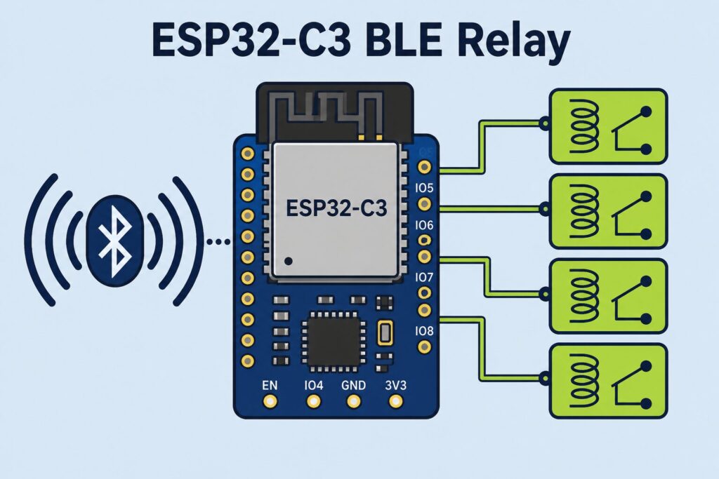
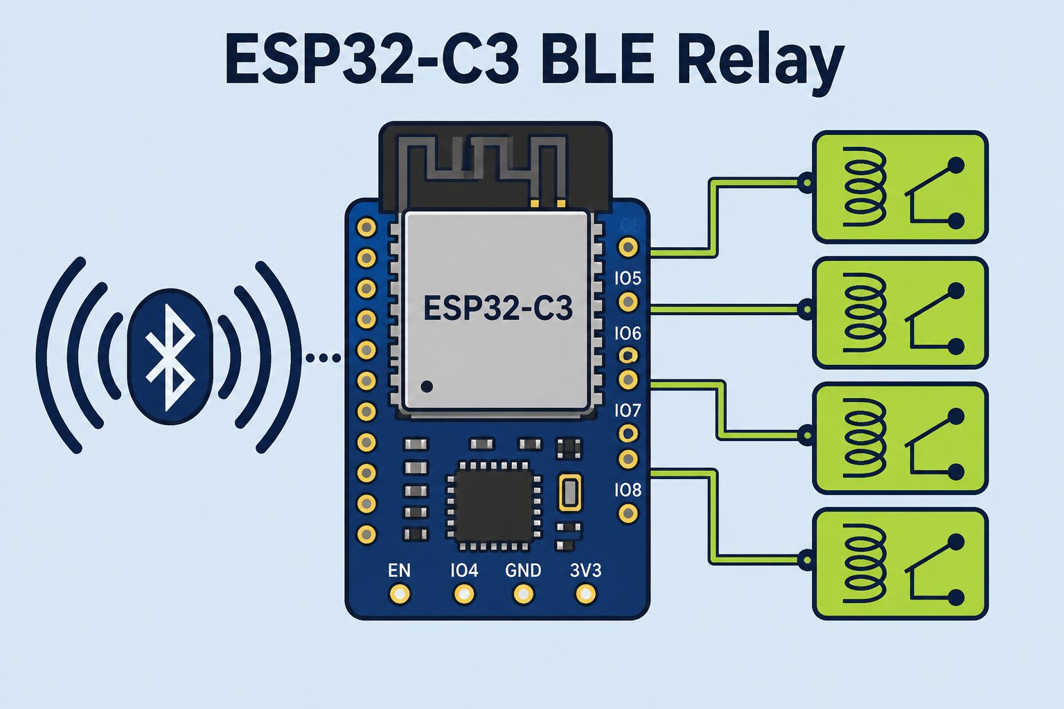
BLE relay control with ESP32-C3 gives product teams a practical architecture for driving industrial relay channels from a phone or tablet at short range. Taking commands over BLE and driving relays via GPIO — without a mandatory Wi-Fi AP or cloud — helps gate, barrier, lighting and auxiliary-contact scenarios on both power and security.
This article summarises the approach Revan Technology uses on field products: the GPIO drive layer, NimBLE service design, command framing and the safety policy applied when the link drops.
Why ESP32-C3?
ESP32-C3 combines a RISC-V core, integrated 2.4 GHz radio and cost-effective BLE in compact control boards. MCU + RF on one chip simplifies antenna and BOM; the NimBLE stack is lighter than Classic BT stacks. In relay control the hard part is not RF — it is reliable GPIO timing, coil drive and fault behaviour, and the C3 provides enough GPIO and timers for that job.
Selection must jointly consider flash size, antenna type (PCB / external), level shifting from 3.3 V logic to a 12 V coil and EMC filtering. “BLE works” does not mean the relay product is done.
GPIO and relay drive layer
Driving a relay directly from an MCU pin is risky in field products. Typical layer: GPIO → driver transistor / ULN / relay driver IC → coil → flyback diode → contact. Load voltage on the contact side (e.g. 12 V / 24 V / mains relay) must be clearly separated from MCU ground. Optocouplers or relay isolation reduce resets and BLE drops on noisy motor loads.
In software, three states per channel suffice: OFF, ON, PULSE. Pulse is a one-shot trigger in the millisecond–second range for gates/barriers; duration travels in the BLE payload. Debounce or a minimum command interval stops double-taps from the app from wearing the mechanical relay.
NimBLE service and command frame
Define a custom GATT service on NimBLE: a command write characteristic (Write / Write Without Response as needed) and a status read / Notify characteristic. Keep the command frame simple:
- sequence number (to distinguish replays)
- opcode (ON / OFF / PULSE / STATUS)
- channel index
- duration or extra parameter
- short checksum / CRC
After handling a command, the board returns the real GPIO/relay state. “Command sent” is not “relay closed”; the app should confirm via Notify. A PIN or simple session key unlocks the command channel after connect; otherwise you advertise an open relay to anyone nearby.
Safety on disconnect
The phone goes into a pocket, range increases or the BLE stack times out. Post-disconnect policy depends on product type:
- All channels OFF: Safe default for lighting / auxiliary loads.
- Hold last state: Conscious choice for continuously running fans.
- Per-channel profile: Gate pulse already ends off; barrier channel forced OFF.
A watchdog recovers a locked main loop, but a watchdog reset must also return to a safe state. Leaving “ignore disconnect in debug” in production means a relay left on in the field.
Field scenarios and testing
Gate motors, barrier hydraulics, 12 V vehicle accessories and panel auxiliary contacts are the most common cases. Antenna attenuation inside metal panels, 12 V alternator noise and long-cable inductance stress BLE and GPIO together. Test checklist: range (open / inside metal), wrong PIN attempts, pulse duration accuracy, channel state after disconnect, reset under 12 V ripple, RS-485 echo consistency if present.
Saying “it opened” from a phone on the desk is not enough; verifying coil drive timing and contact bounce with a scope or logic analyser reduces warranty calls.
Gains
A correctly built BLE relay control with ESP32-C3 architecture removes cloud dependency, limits access with a PIN, raises operator confidence with status feedback and prepares the ground for OTA / version gates. In Revan Technology projects these layers are designed together with PCB, firmware and Flutter app — yielding a productisable control unit rather than a kit assembly.
Results
ESP32-C3 is a strong core for BLE relay products on cost and integration. Success depends on locking NimBLE service design, a solid command frame, GPIO drive engineering and disconnect safety policy together. If the answer to “link dropped — what did the relay do?” is not written up front, risk remains on site no matter how polished the phone UI looks.
🔗 Get in touch with us:
Phone/WhatsApp: +41 76 212 8248
📧 E-Mail: info@revantechnology.ch
For detailed information about our services in electronics development & PCB design:
Revan Technology – Your partner for professional electronics and PCB development