 Veysi Filiz
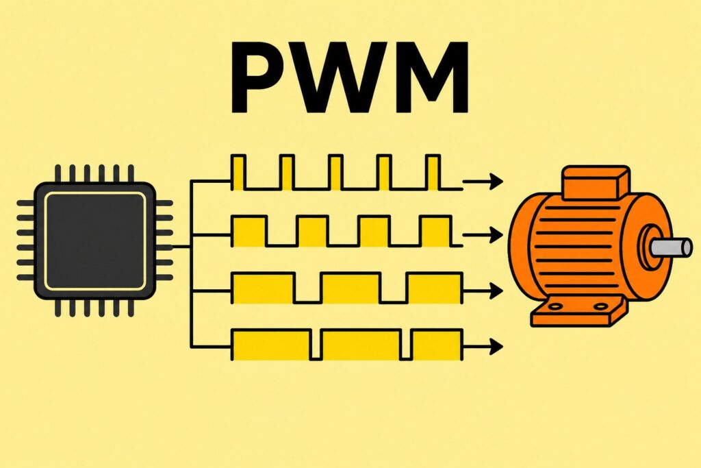
PWM DC motor control is one of the most widely used speed management methods on industrial embedded boards. With a fixed supply voltage, pulse-width modulation (PWM) adjusts the average motor terminal voltage to control speed smoothly. In Revan Technology projects this approach delivers more efficient and measurable results than mechanical regulators or simple on-off relay solutions for conveyors, pumps, fans and actuators.
A properly designed PWM driver layer combined with current limiting, direction reversal (H-bridge), back-EMF protection and software ramping significantly reduces the risk of motor faults and driver damage in the field.

PWM DC motor control — definition
PWM (Pulse Width Modulation) generates pulses at a fixed frequency and changes the duty cycle to adjust the effective voltage on the load. For a DC motor, average terminal voltage increases with rotor speed; current in the opposite direction reverses rotation.
In a typical embedded application a microcontroller timer unit produces the PWM output; the signal is passed to the motor via a MOSFET driver IC or discrete H-bridge. Frequency selection balances motor inductance, mechanical noise and efficiency; on industrial boards the range is usually a few kHz to tens of kHz.
Problem context
In field panels and machine control boards DC motor control is often limited to the question “does it run?”. In practice these issues appear frequently:
- Sudden acceleration: Motor and mechanical load cause current spikes with un-ramped PWM transitions; the driver heats up or protection trips.
- Back-EMF: When the motor stops or changes direction, inductive voltage can damage MOSFETs; missing flyback diodes or active braking become failure sources.
- Current overrun: A jammed conveyor, locked pump or high torque demand at low speed pushes the driver above its thermal limit.
- EMI and noise: High frequency, long motor cables and poor grounding create interference on the line and corrupt sensor readings.
- Direction change dead time: Both legs of an H-bridge conducting at once (shoot-through) causes a short circuit.
Generating a PWM signal alone is therefore not enough; driver topology, protection and software policy must be designed together.
Technical analysis
Frequency and duty cycle. At low frequency motor current is pulsed and mechanical vibration increases. At high frequency switching losses grow. For motors with high inductance a minimum frequency is calculated so current flows smoothly over one PWM period. Duty cycle may not be linear between 0% and full speed; a “compensation curve” in software can offset torque drop at low speeds.
Driver topology. Single-direction applications may use a low-side or high-side MOSFET. Two-direction motion uses an H-bridge (full bridge); the driver IC adds dead time to prevent shoot-through. Current sensing (shunt resistor or Hall) enables limiting, stall detection and soft start.
Protection layers. Flyback diodes, TVS or snubber, thermal shutdown and current limit require hardware/software coordination. On direction change, brief dynamic braking or coast mode is chosen per scenario.
Software ramp. A linear or curved ramp to the target duty cycle instead of a step reduces mechanical and electrical stress. Closed-loop speed control with PID adds an encoder or back-EMF measurement when needed.
Field scenarios
Conveyor speed adjustment. On packaging lines belt speed changes with product type. Smooth PWM adjustment is synchronised from an operator panel or PLC command. Ramp time on stop-start cycles prevents product tipping.
Dosing pump. On peristaltic or diaphragm pumps flow is proportional to motor speed. Current limit in low-flow mode prevents dry running; stall detection triggers alarm and safe stop.
Fan and cooling. PWM tied to a temperature sensor reduces noise and energy use versus fixed full speed. Hysteresis is defined if the motor would stall below minimum duty.
Linear actuator / door drive. Open-close limits are protected by limit switches; brief braking on direction change reduces mechanical impact.
Solution approaches
Revan Technology board designs address PWM motor control in these steps:
1. Clarify load profile: Nominal current, stall current, supply voltage range and cable length are defined.
2. Topology choice: Single / dual direction, integrated driver (e.g. half-bridge driver IC) or discrete MOSFET; thermal calculation is performed.
3. PWM parameters: Frequency, resolution (timer bit depth), minimum/maximum duty and ramp time are defined.
4. Protection: Current limit, thermal, back-EMF, cable break (open circuit) and short-circuit scenarios are tested.
5. EMI: Twisted pair on the motor line, ferrite, proper ground reference and separation of driver and MCU.
6. Verification: Oscilloscope checks for shoot-through, current profile and duty-speed relationship; thermal and noise tests under field conditions.
When speed command arrives via external HMI or Modbus, the local board applies the ramp; if communication is lost, the last safe setpoint or fail-safe stop policy takes over.
Benefits
- Smooth speed adjustment; reduces need for mechanical valves or gear stages.
- Energy efficiency: power on demand instead of full speed; noticeable savings on fan and pump applications.
- Measurability: duty cycle, current and fault codes are logged for maintenance planning.
- Integrated protection: stall, overcurrent and thermal events are forwarded to the central alarm system.
- PLC/HMI compatibility: integration with existing automation via analog 0–10 V or digital setpoint.
Industry observation / experience
In industrial sites PWM motor boards often go to series because they “worked on the first prototype”; yet long cables, low temperature and dusty environments behave differently. In Revan projects the most common second-wave issues are: insufficient dead-time setting, motor cable routed in the same tray as signal lines, and software ramp disabled on operator “full speed” commands.
The right frequency choice also affects audible noise; choosing above 20 kHz on packaging lines improves operator comfort. A current sensor looks like extra cost but prevents a set of driver MOSFETs from burning and avoids unplanned downtime cost.
Conclusion
PWM DC motor control looks simple on embedded industrial boards but requires driver, protection and software discipline. When frequency, ramp, H-bridge dead time and current limit are designed together, conveyors, pumps, fans and actuator applications run reliably and efficiently. Clarifying load profile and field cable conditions at the start of a new motor control board project greatly reduces later hardware revisions.
🔗 Get in touch with us:
Phone/WhatsApp: +41 76 212 8248
📧 E-Mail: info@revantechnology.ch
For detailed information about our services in electronics development & PCB design:
Revan Technology – Your partner for professional electronics and PCB development