 Emre Ceylan
Optocoupler industrial isolation is a fundamental protection method that provides galvanic separation between field-side sensors, relays, and driver circuits and the microcontroller or PLC input layer via an optical path. In industrial panels, different ground potentials, long cable runs, and sudden voltage spikes can cause measurement errors, resets, or permanent damage if they reach the control board directly. In Revan Technology projects, the optocoupler is a standard design component in digital input modules, emergency stop chain reading, and communication line isolation.
When the correct CTR value, response time, and driver resistance are selected, the optocoupler increases EMI immunity while making the circuit independent of field voltage.
Optocoupler industrial isolation — definition
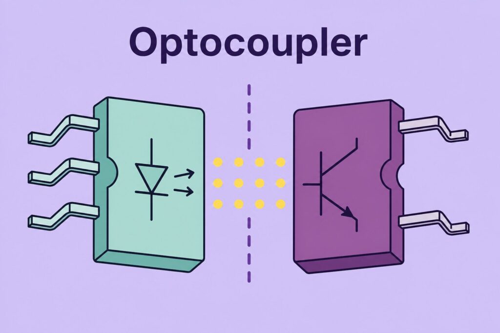
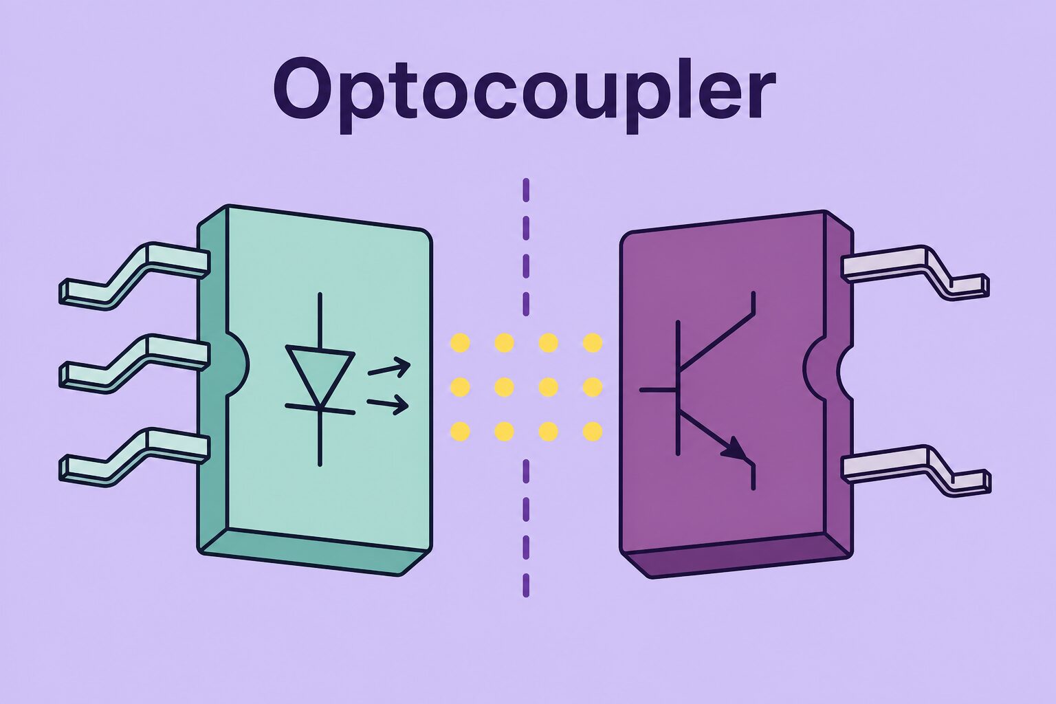
An optocoupler (photocoupler) is an electrically isolated coupler with optical connection between the LED side and the photodiode or phototransistor side. When current is applied to the input side, the LED turns on; the photo element on the output side becomes conductive. Only light energy is transferred between the two sides; there is no direct conductive path.
Typical use in industrial boards: converting a 24 V field sensor to a 3.3 V MCU input, separating a relay driver from control logic, or creating an additional isolation layer between an RS-485 transceiver and the processor. Product range spans from single-channel DIP packages to multi-channel SOIC ICs; isolation voltage (e.g. 2500–5000 Vrms) and CTR (Current Transfer Ratio) are specified in the datasheet.
Problem context
In field panels and machine control boards, lack of isolation is often not noticed in the first test; it appears after long cables, ground differences, or lightning-induced events. Common problems include:
- Ground loop: If field equipment and the control board have different ground references, common-mode voltage couples onto input pins; false readings or latch-up risk arises.
- High-voltage leakage: When a relay coil is switched off, a motor contactor fails, or cable damage occurs, field-side voltage can reach the low-voltage circuit.
- EMI coupling: Long sensor cables and power lines cause pulses and oscillating false triggers on digital inputs.
- CTR drop: If LED current is insufficient or the optocoupler ages, the output may not conduct enough; intermittent “sometimes works” failures occur.
- Slow response: Wrong optocoupler selection in high-speed counting or encoder reading causes signal distortion.
Therefore the “we connected direct GPIO, it works” approach is not sustainable in industrial environments; isolation and limiting must be designed together.
Technical analysis
CTR and LED current. CTR is the ratio of phototransistor collector current to LED current. Series resistance on the LED side is calculated from the minimum CTR value; logic level on the output side is formed with pull-up or pull-down. Temperature and aging reduce CTR; leaving 30–50% margin in design is safe practice.
Response time and bandwidth. Rise/fall time is critical in applications requiring pulse width modulation or high-frequency counting. Microsecond range may suffice for general digital inputs; photodiode output or high-speed optocouplers are preferred for fast encoder reading.
Isolation voltage and creepage/clearance. Datasheet isolation voltage must be supported by isolation distance on the PCB (creepage, clearance). If high-voltage field circuits and low-voltage layers share the same PCB, slots or cut isolation barriers are applied.
Topology selection. Phototransistor output models suit simple digital reading. Schmitt trigger buffer (e.g. 74HC14) can be added to reduce pulse distortion. On multi-channel boards, per-channel limiting is preferred over shared LED supply.
Alternatives. In addition to optocouplers, digital isolators (capacitive/magnetic) can offer higher speed and integrated power isolation; cost and complexity increase. In simple 24 V digital input modules, the optocoupler remains a cost-effective, proven solution.
Field scenarios
24 V PNP/NPN sensor input. Industrial proximity or limit switch output is connected to the optocoupler LED side with limited current; the MCU side is read at 3.3 V logic level. In cable break and short-circuit scenarios, field voltage does not reach the processor pin.
Emergency stop (E-stop) reading. When dual-channel reading is required in a safety chain, each channel is isolated with a separate optocoupler; ground potential differences do not affect safety logic.
Relay and contactor driving. The driver line from the control board to the relay coil is separated by an optocoupler; coil back-EMF and switching noise are not coupled to the MCU side.
Long-distance communication pre-isolation. If an isolated communication module is not used before RS-485 or CAN transceivers, at least critical control lines can be locally protected with optocouplers.
Solution approaches
Revan Technology board designs apply optocoupler industrial isolation in these steps:
1. Field profile: Supply voltage (24 VDC / 230 VAC relay), cable length, grounding structure, and expected noise level are defined.
2. Optocoupler selection: Isolation voltage, channel count, CTR, speed, and package (DIP/SOIC) criteria are clarified.
3. LED side calculation: Series resistor, reverse parallel protection diode (for AC or inductive load), and current limit are calculated.
4. Output side: Pull-up value, logic level compatibility, and Schmitt trigger or RC filter if needed.
5. PCB layout: Field and logic side separation, isolation distance, ground partitioning (split ground).
6. Verification: Isolation test, EMI scan, function test at CTR limit (low LED current), and temperature cycling.
In series production, optocoupler lot differences cause CTR spread; the same series resistor value is chosen to leave sufficient margin on all boards.
Benefits
- Galvanic separation prevents field voltage and ground differences from reaching the control layer.
- Digital input immunity to EMI and switching noise increases.
- Risk of “burned board” in maintenance and fault analysis decreases; field-side events stay isolated.
- 24 V industrial standard is safely bridged to 3.3 V/5 V logic domain.
- Repeatable, measurable design per channel in multi-point I/O modules.
Industry observation / experience
In industrial fields, having an optocoupler “only on the input board” is often considered enough; yet output drivers and communication lines carry the same risk. In Revan projects, second-wave issues often stem from narrow CTR margin, LED current calculated for nominal 24 V but insufficient under real field voltage drop, and long cable capacitance lengthening edge times.
Also, when a long cable is connected directly to the optocoupler output, capacitive load extends response time; input buffer or filter values must be validated in field tests. In legacy panels with single-point grounding, the isolation layer is a silent enabler of compatibility in modern PLC integration.
Conclusion
Optocoupler industrial isolation is a simple, low-cost yet critical safety and reliability layer on embedded control boards. When correct CTR calculation, PCB isolation distance, and field-logic side separation are applied together, faults from ground loops, noise, and voltage leakage decrease significantly. Planning isolation from the start in a new digital I/O or field interface board design, rather than adding it later, reduces field commissioning time and warranty costs.
🔗 Get in touch with us:
Phone/WhatsApp: +41 76 212 8248
📧 E-Mail: info@revantechnology.ch
For detailed information about our services in electronics development & PCB design:
Revan Technology – Your partner for professional electronics and PCB development